Part Setup
Import, orient, scale, arrange and validate the CAD model inside the virtual build environment.
The digital bridge between your CAD model and the manufacturing cell. SETU brings part setup, slicing, advanced deposition planning, robot simulation and robot-ready program generation into one connected workflow.
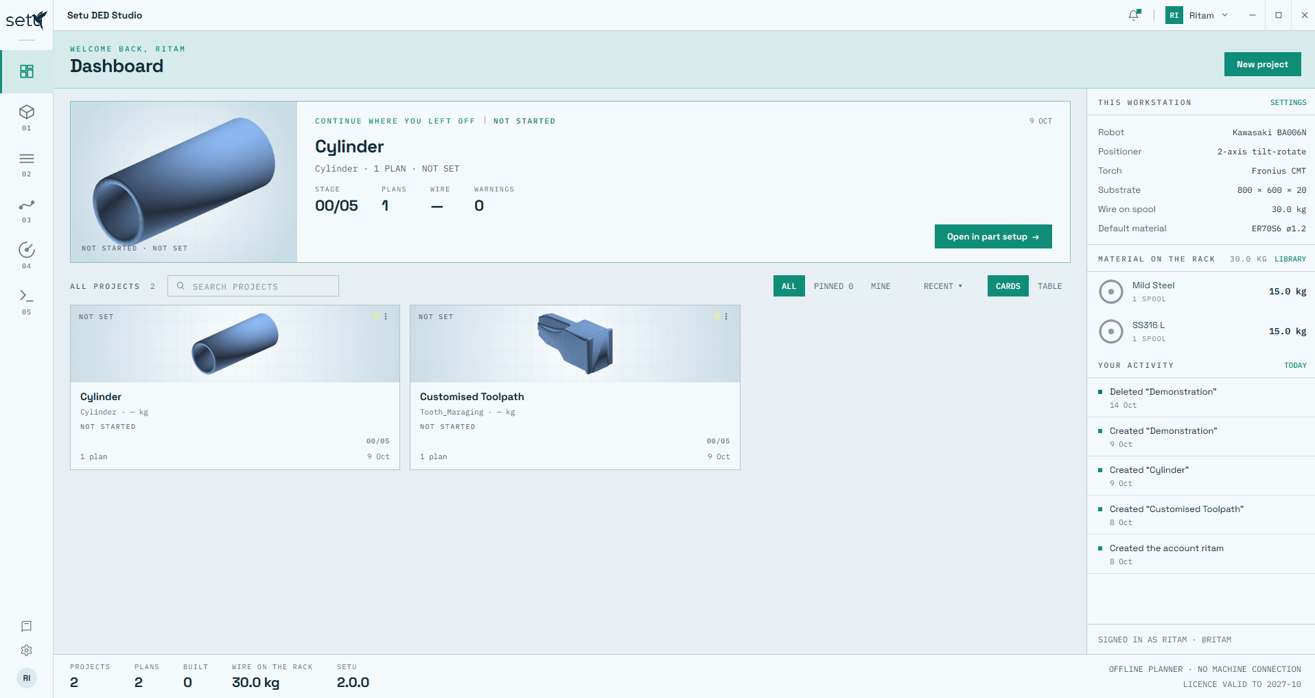
SETU organizes the complete additive-manufacturing planning sequence into five clear stages, while retaining project history, material inventory and machine configuration in the same workspace.
Import, orient, scale, arrange and validate the CAD model inside the virtual build environment.
Planar or skeleton slicing, custom Z ranges, machining allowance and region-wise layer control.
Choose deposition strategies, process parameters, thermal/travel logic and inspect every layer.
Run robot inverse kinematics, reach and joint-limit checks before entering the physical cell.
Post-process, inspect, edit and export robot-specific programs for manufacturing.
SETU sign-in and user workspace flow.
SETU supports individual user accounts so people sharing the same workstation can work within their own project space. Standard users do not see one another's project lists, while an administrator can centrally manage and remove user accounts when required.
Dashboard: projects, workstation configuration, feedstock inventory and activity history.
After sign-in, SETU presents the user's projects, the latest unfinished job, configured robotic cell, available feedstock and recent activity in one place. The dashboard is designed to let a user resume planning without searching across separate applications or records.
SETU estimates material requirements from the imported component geometry and keeps the feedstock inventory visible throughout the planning workflow.
Import the CAD model and prepare its position, orientation, scale, material and substrate arrangement before slicing. The virtual arrangement can be matched to the intended real manufacturing setup for better process visualization and downstream robot simulation.
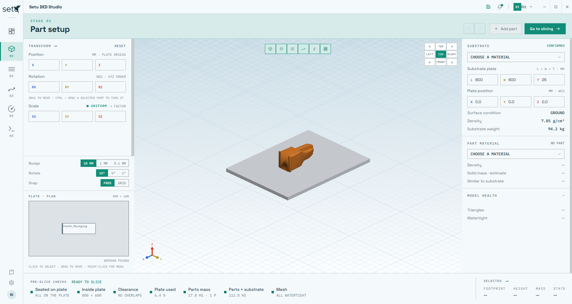
Translate, rotate and orient parts inside the virtual cell, apply uniform or axis-dependent scaling, and place the component directly on the defined substrate. A top-view plan allows parts to be selected and dragged across the plate for fast arrangement.
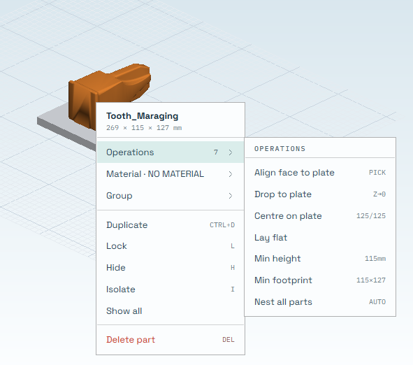
Align a selected face to the plate, drop the model to the substrate, centre it, lay it flat, minimize build height or footprint, and automatically nest multiple parts.
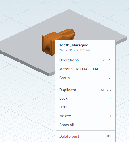
Import multiple CAD models, duplicate parts for batch production, group or isolate models, and plan them on a common substrate. Individual models can later use different slicing and process parameters.
Manual and one-click orientation tools help the user search for arrangements that reduce build height, minimize substrate footprint or reduce the need for support structures before process planning begins.
SETU provides planar and skeleton-based slicing workflows, with control over layer height, shell-only deposition, machining allowance, local Z ranges and region-based variable layer thickness.
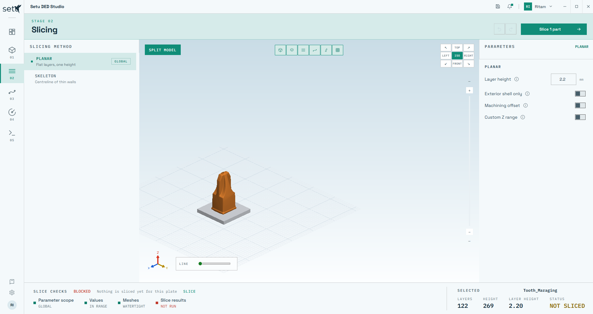
Planar slicing supports general component geometries using flat layers with a defined layer height. Skeleton slicing is intended for thick- and thin-walled structures using wall centrelines.
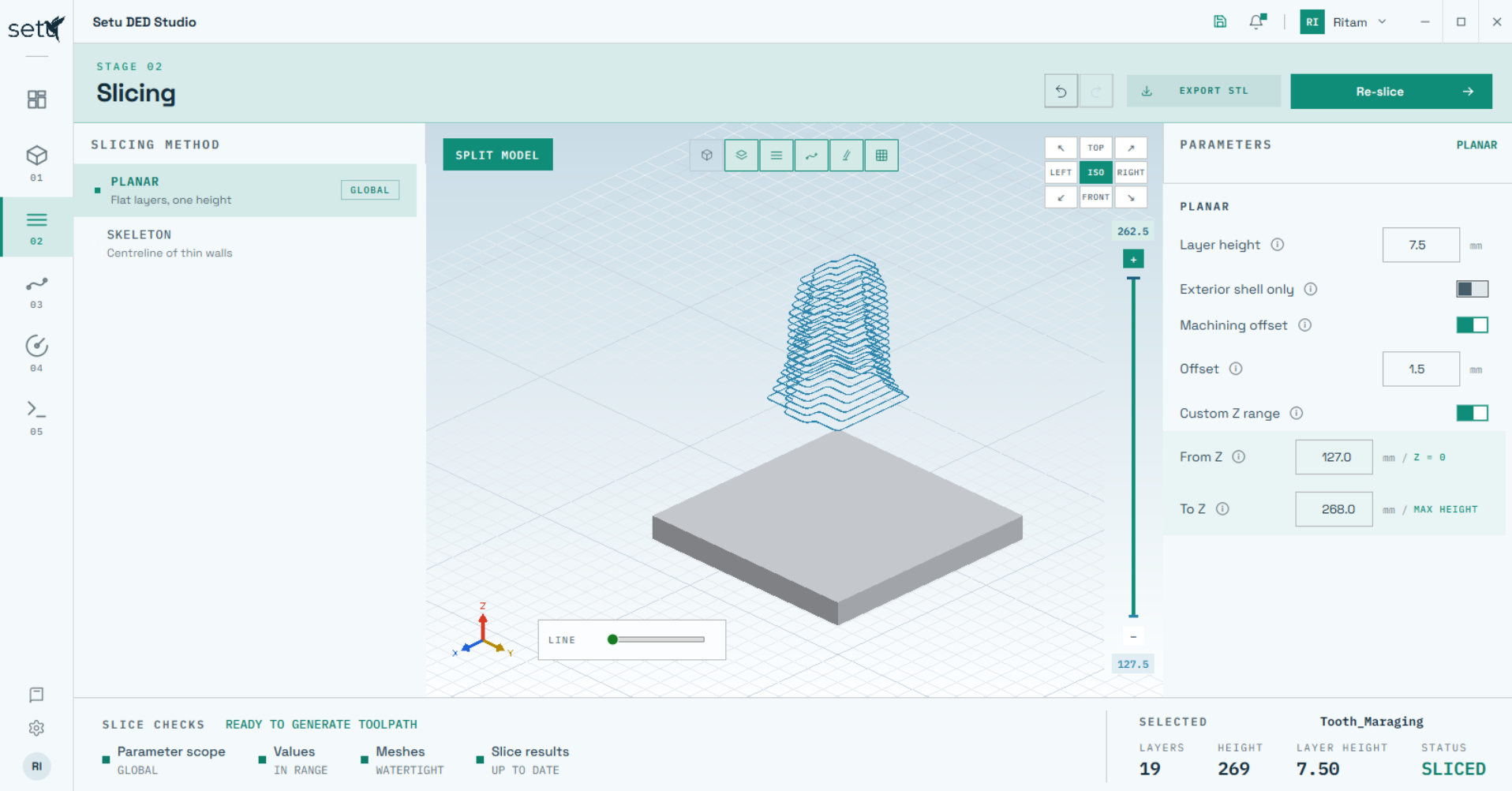
Limit slicing to the required Z interval instead of processing the complete model—useful for repair and remanufacturing.
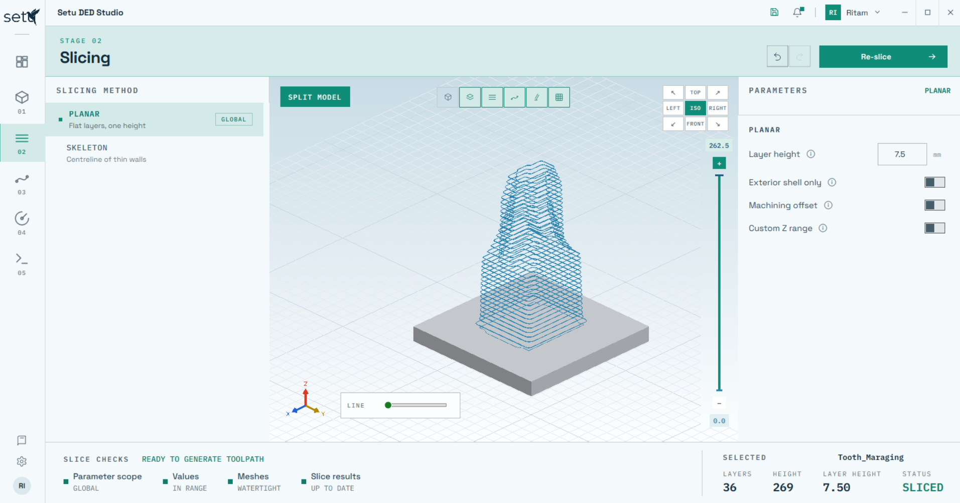
Inspect generated layers in the 3D viewport and review layer count, component height, layer thickness and slicing status.
Split-model slicing demonstration.
Split a model into multiple build regions and independently assign the layer thickness in each region. Finer layers can be retained where geometric resolution is important, while larger layers can be used where higher deposition productivity is preferred.
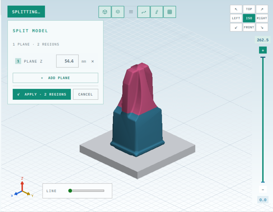
Create build regions at user-selected heights before assigning regional slicing parameters.
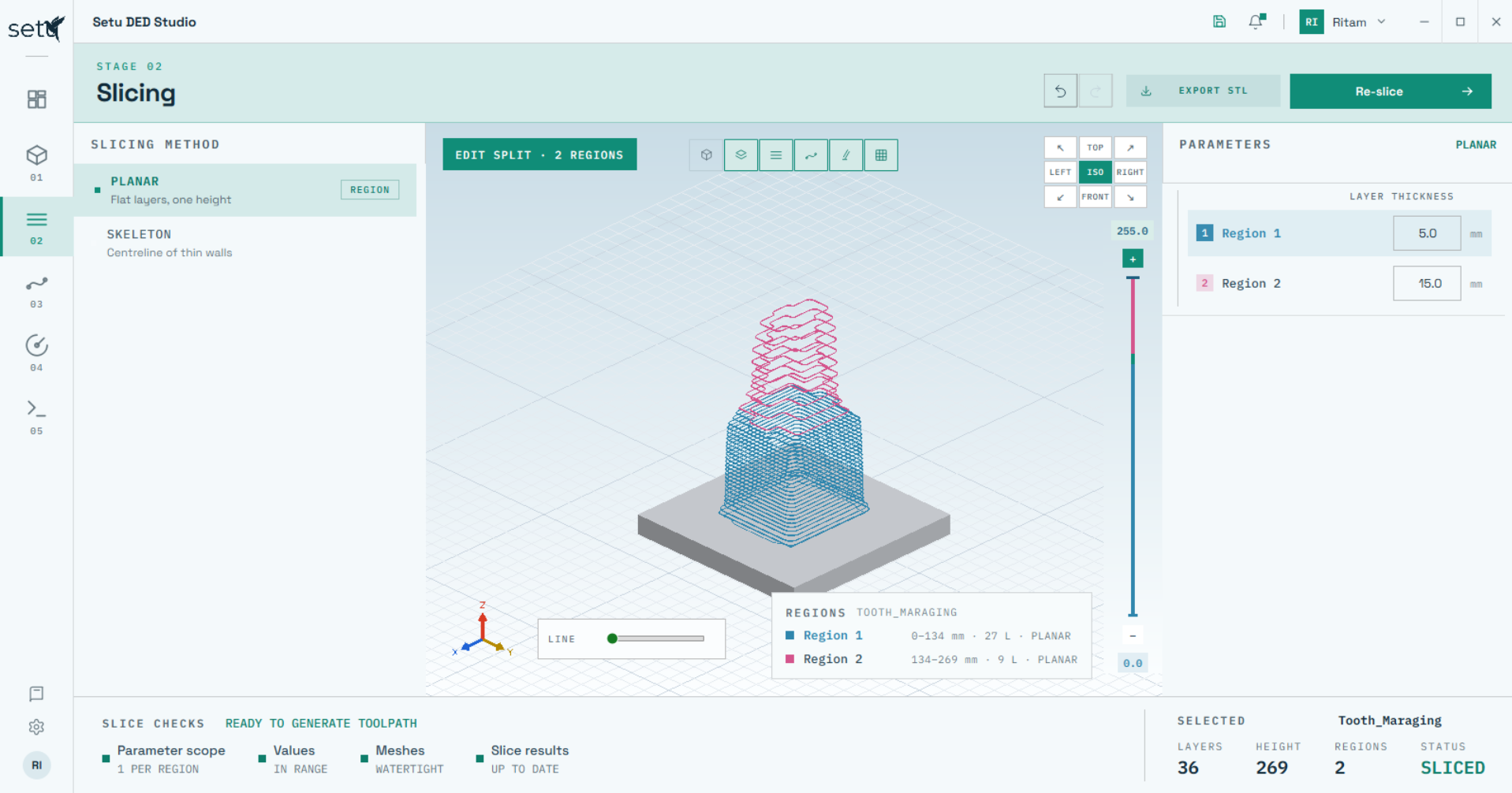
The example shows two zones using different layer thicknesses and clearly separated in the viewport.
Define the deposition strategy and process-planning parameters for each region, inspect the generated trajectory layer-by-layer, and compare alternatives before committing to the build.
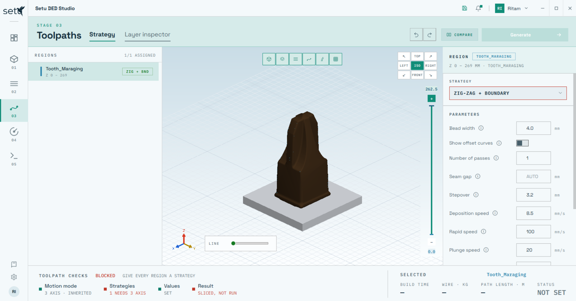
SETU exposes the planning parameters that govern path spacing, motion and inter-layer travel directly beside the 3D model so changes can be evaluated within the same environment.
Lift/linking behaviour can be selected for minimum travel time or for minimum heat gradient, helping the planner prioritize productivity or reduce localized heat accumulation.
Raster-style infill for general area filling, with boundary variants available when an outer outline is required.
Precise, discrete material placement for geometries and deposition situations requiring localized control.
Designed for high-deposition applications while promoting more uniform mechanical properties in all three principal directions.
Combines precise DOD deposition with raster filling to realize overhanging geometries without conventional support structures.
Hybrid DOD + Zig-Zag toolpath demonstration.
Generated trajectories are visualized directly on the component. SETU reports practical planning outputs such as estimated build time, material requirement and path length so the user can evaluate a strategy before simulation or code generation.
Layer Inspector demonstration.
Move through the build layer-by-layer and verify the deposition trajectory instead of accepting a complete toolpath as a single opaque result. The Layer Inspector shows boundaries, toolpath lines, weld-start points and weld-off points for each selected layer.
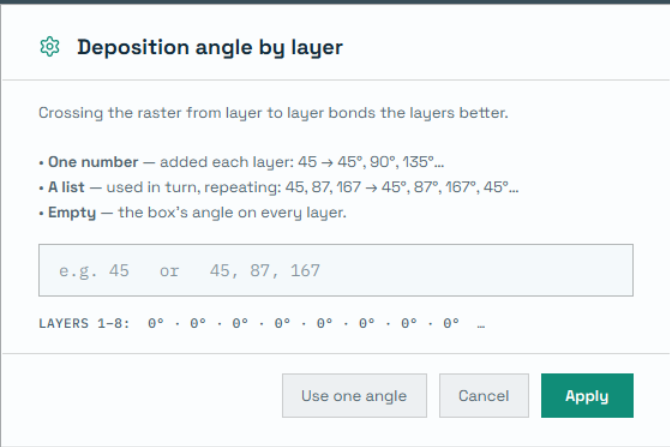
Define a constant angular increment from layer to layer, or enter a custom sequence of deposition angles that repeats through the build. This gives the user direct control over raster orientation and layer crossing.
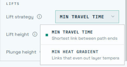
Choose shortest-link routing for minimum travel time or heat-aware linking intended to even out layer temperature.
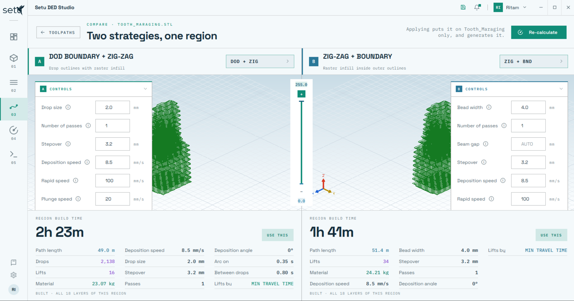
Evaluate two toolpath strategies simultaneously instead of generating them in separate workflows and comparing results manually. SETU places both alternatives side-by-side with their key manufacturing metrics.
Load the required robot, solve the inverse kinematics and simulate the planned deposition sequence inside the virtual cell. Reachability, joint behaviour and potential motion issues can be checked before the job is transferred to the physical robot.
Robot simulation excerpt.
SETU displays the robot configuration and joint angles while the build is simulated. Joint limits can be imposed or adjusted, and the reach-check function helps verify whether the planned component location is accessible to the selected robot.
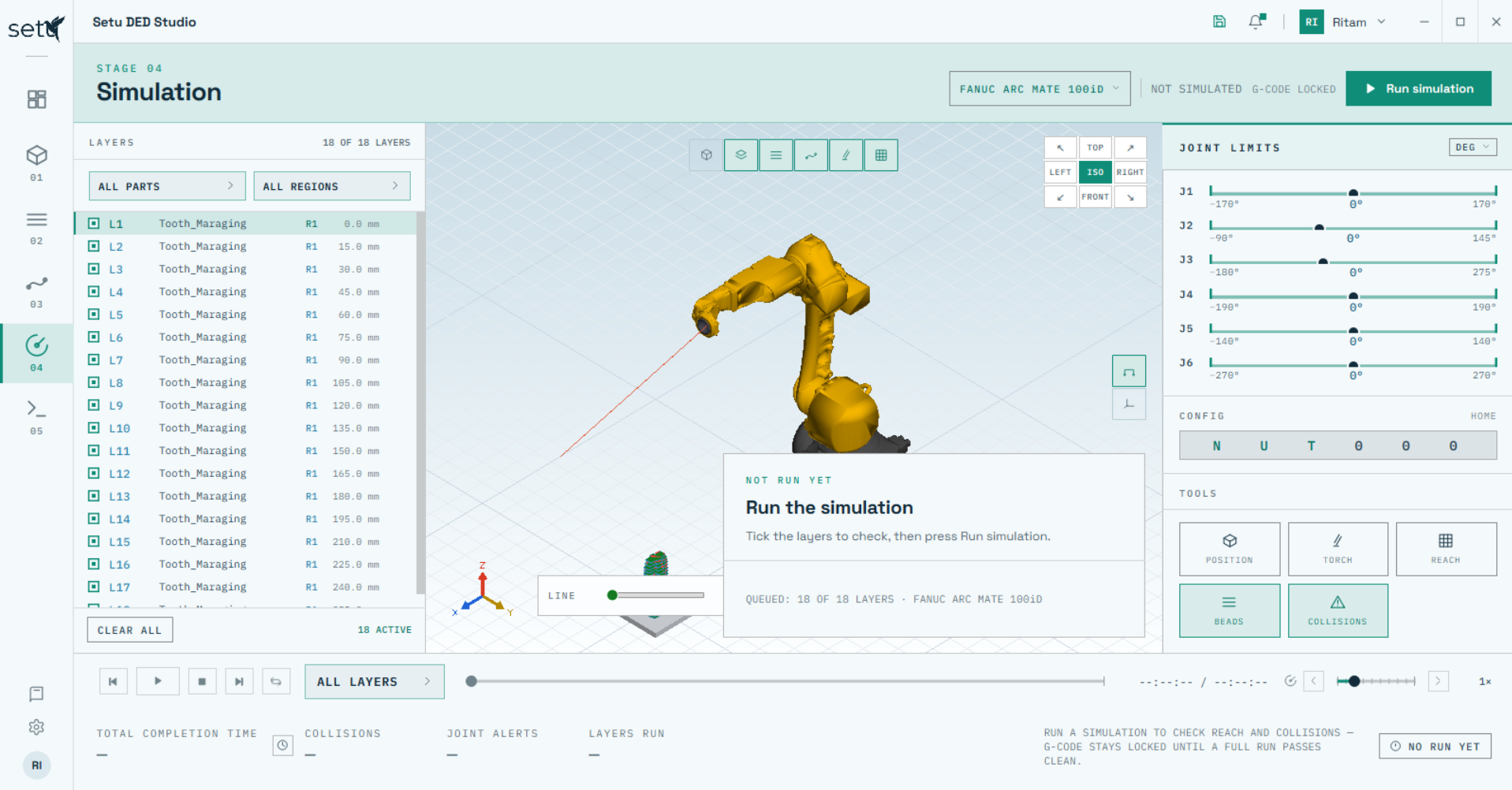
Track J1–J6 motion, impose allowable limits and evaluate robot reach from the same simulation page.
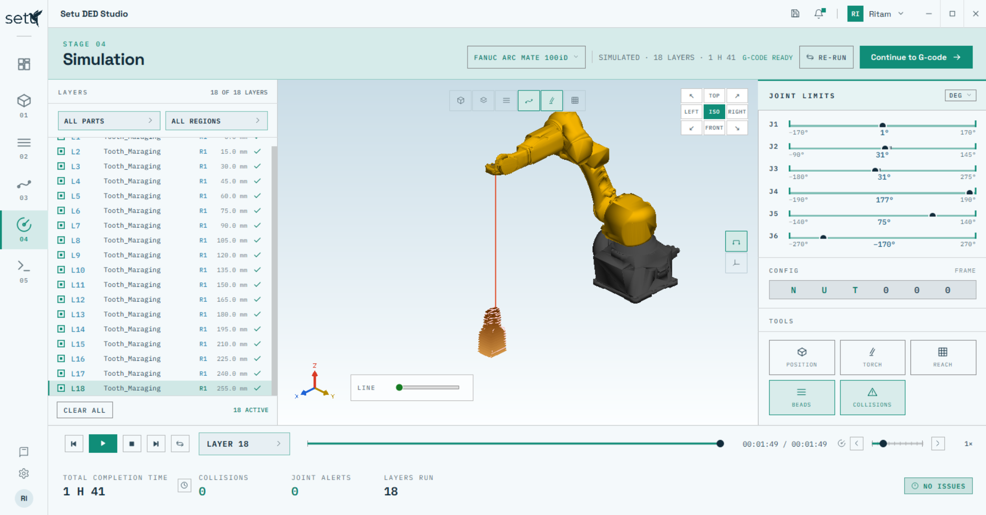
Review completion time, collisions, joint alerts and the number of simulated layers before moving forward.
After successful simulation, select the appropriate post-processor, define the required robot-program variables and generate the machine-ready output. The resulting program can be reviewed and edited directly in SETU before transfer.
Robot-code generation excerpt.
SETU can generate robot-specific output through the configured post-processor and gives the user direct visibility of the resulting code. Programs can be organized at different levels depending on the build and controller workflow.
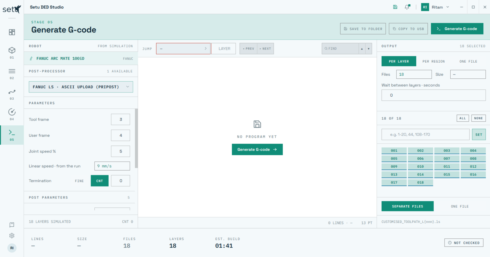
Choose the relevant robot/post-processor pair, controller variables and output organization before generation.
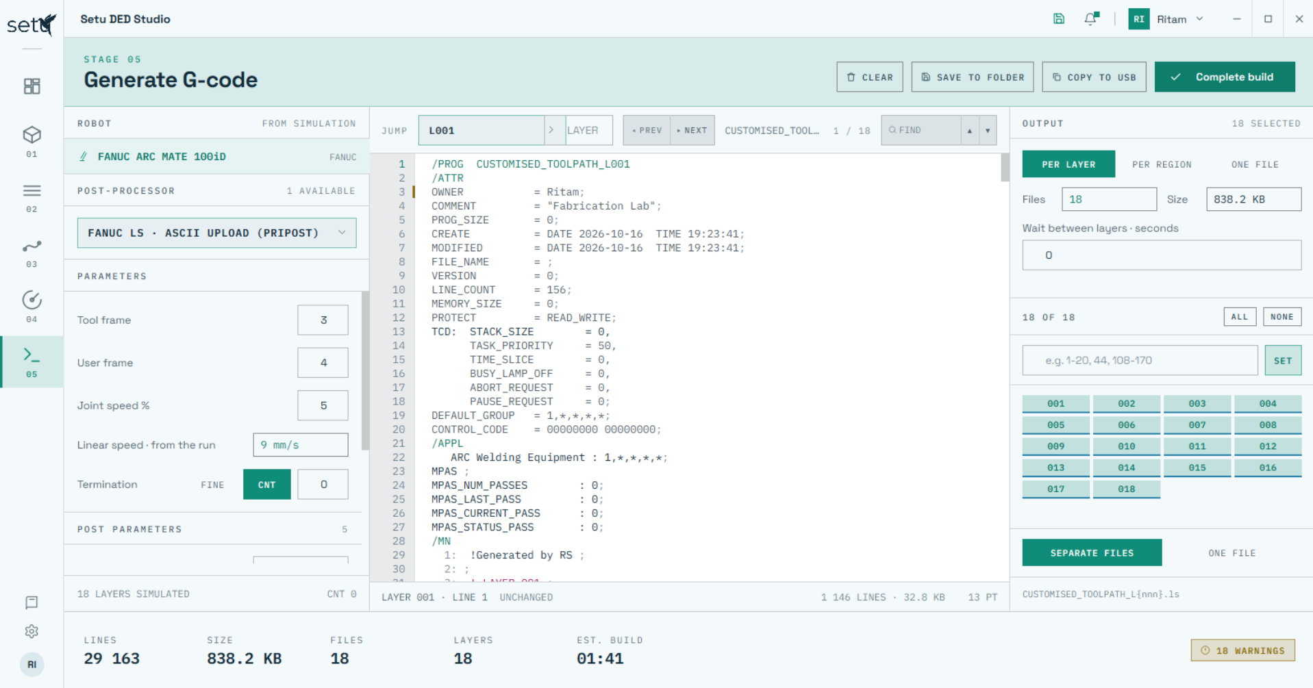
Read and modify the generated controller program in SETU, while monitoring file size, line count and warnings.
Displaying the generated program size and line count helps the user plan the output structure around the memory and file-handling constraints of the target robot controller.
Beyond the five planning stages, SETU includes practical utilities for feedstock management, robot/TCP configuration, display preferences and file-directory control.
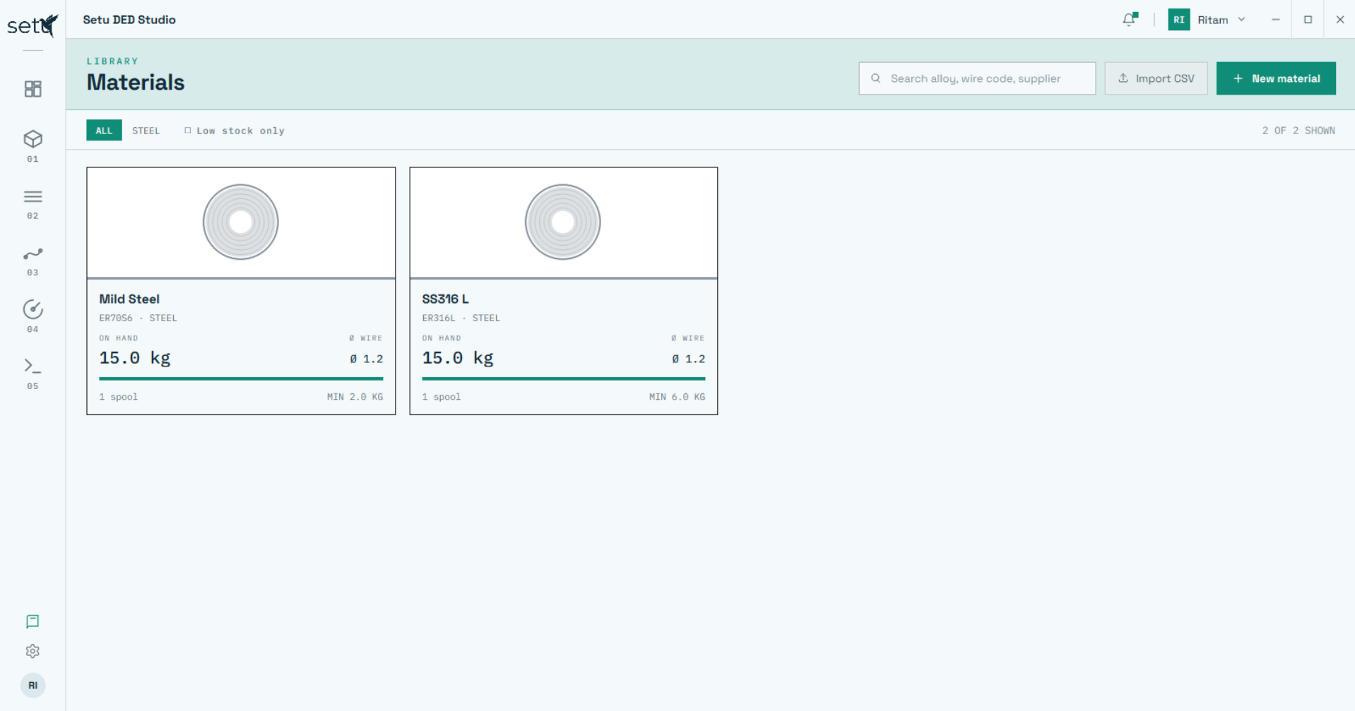
Add material/spool entries, maintain available quantity and search the material library. The library supports the dashboard's feedstock tracking and material-aware planning workflow.
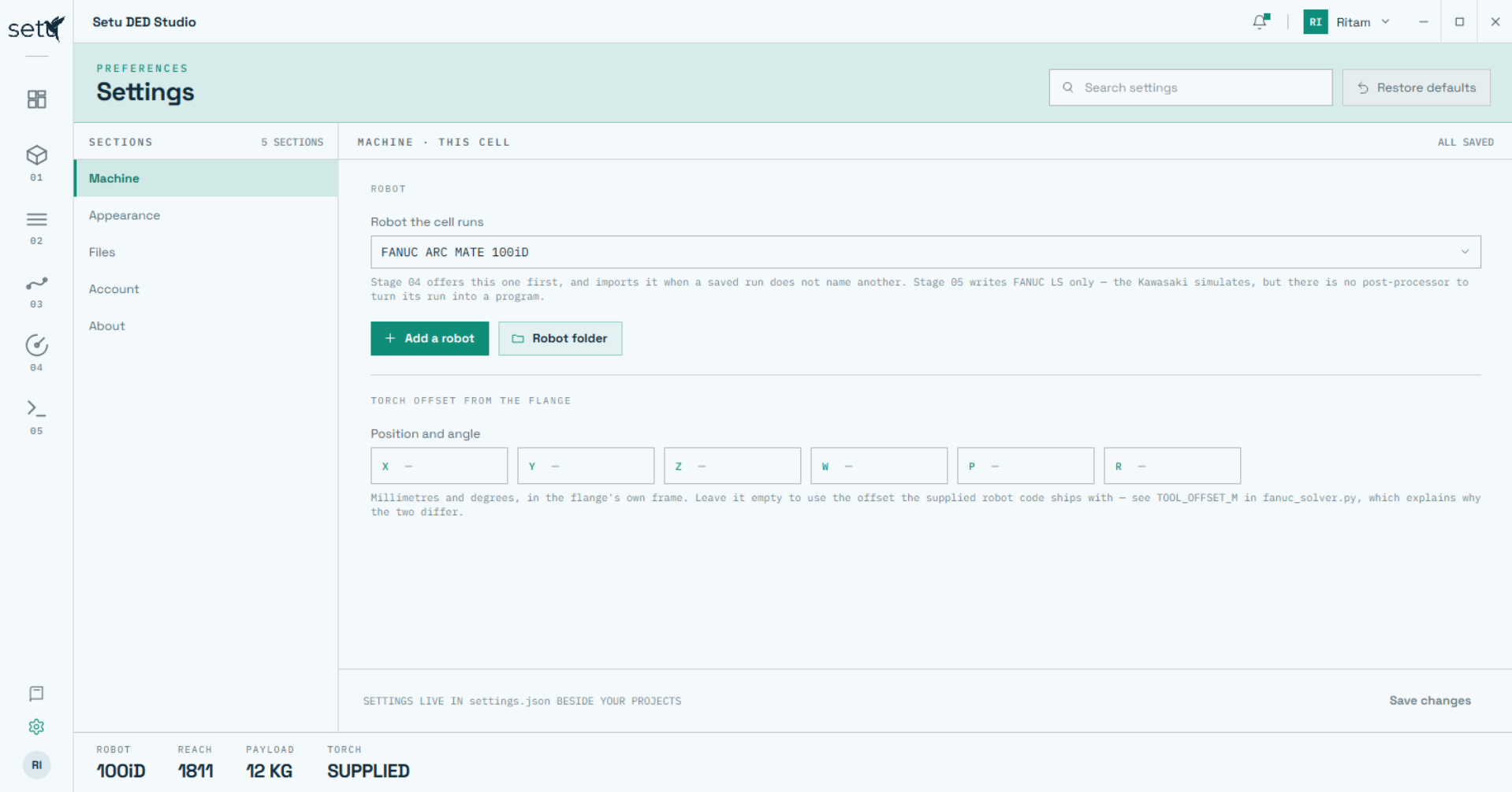
Select the robot used by the cell, add/import another robot configuration and define the torch/tool centre point offset relative to the robot flange.
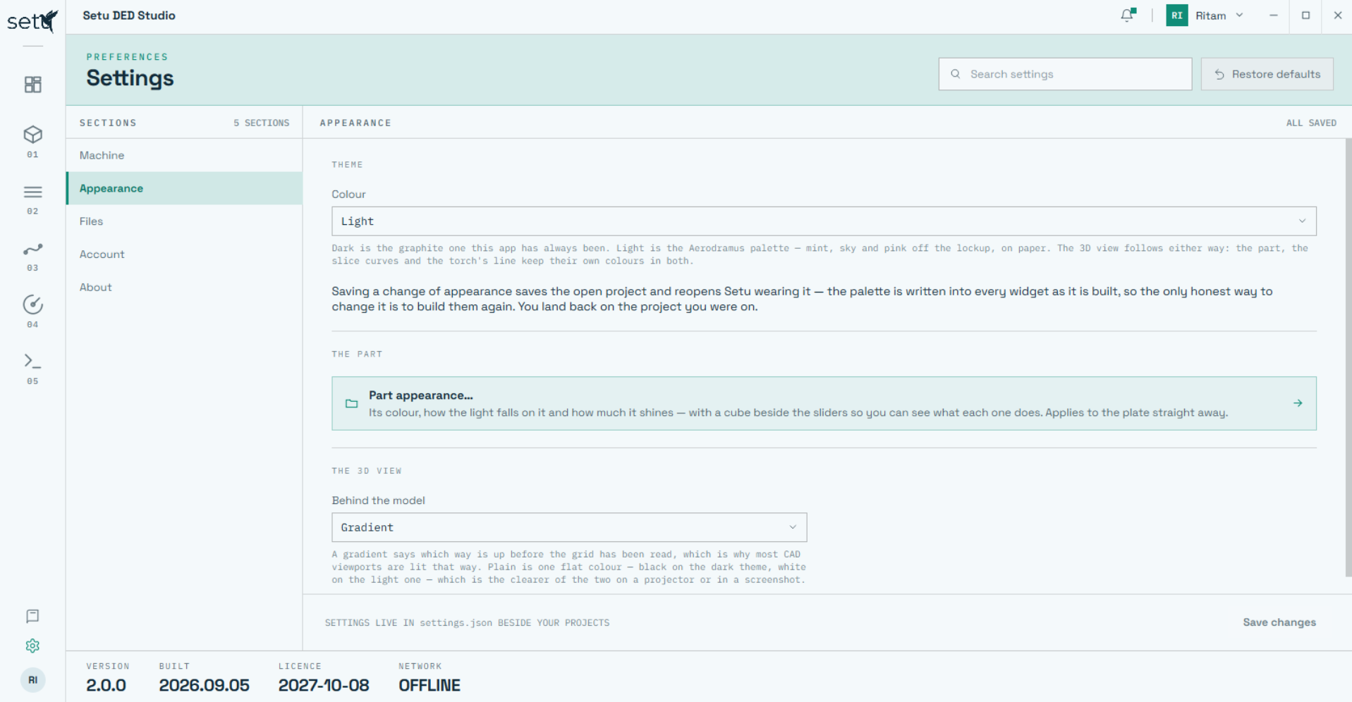
Switch between light and dark interface modes, control part/display appearance and tessellation accuracy, and define the directory locations SETU uses for project and output files.
SETU is designed to reduce the hand-offs between geometry preparation, deposition planning, process evaluation and robotic execution—while keeping the user in control of the parameters that matter.
Orientation, scaling, substrate planning, multi-part arrangement and pre-slice checks.
Flexible slicing, patented toolpaths, thermal/travel logic and process parameter control.
Inspect every layer and compare alternative strategies using time, material and path metrics.
Robot simulation, reach/joint checks, post-processing, code inspection and export.
Talk to Aerodramus about WAAM/DED process planning, advanced toolpaths, robotic automation, repair workflows or a tailored SETU demonstration using your component geometry.
Request a SETU Demo →